36+ Stepper Motor Diagram
We will cover the basic working principles of stepper motors their driving modes. NEMA motors and can-stack or tin-can steppers.
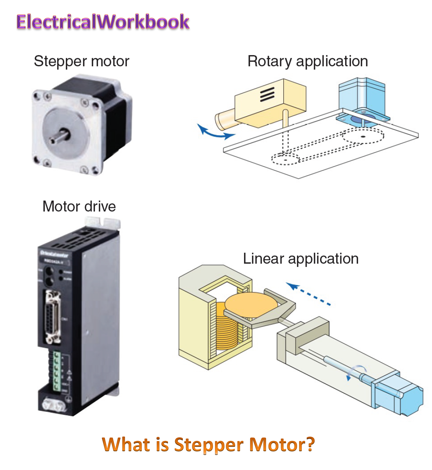
Stepper Motor Working Diagram Types Characteristics Applications Electricalworkbook
33 CL86T is recommended for.

. Permanent Magnet Stepper. Web Stepper motors are used extensively in industrial automation robotics 3D printers CNC machines and many other applications requiring precise positioning and speed control. 31 CL42T is recommended for NEMA17 or smaller closed loop stepper motors and the driving voltage is recommended to be 24V.
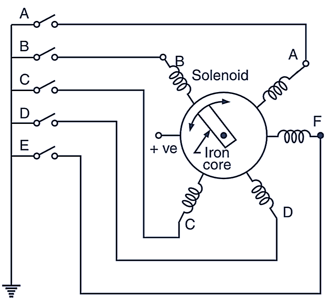
Web 32 CL57T is recommended for NEMA23 or 24 closed loop stepper motors and the driving voltage is recommended to be 2448V. Web Stepper Motor Winding The stepper motor is generally constructed using two electromagnets as shown in below Bipolar Wound Stepper Motor diagram. You will learn about the working principles construction control methods uses and types of stepper motors as well as.
The stepper is controlled by with digital pins 8 9 10 and 11 for either. Browse discover thousands of brands. The rotor and stator poles of a permanent magnet stepper are not teethed.
Web There are two common families of stepper motor that youll encounter. The 6-wire motor the most common arrangement is intended for. The labs on this site can work with either.
Although there are a number of different components within a stepper motor that have a large impact on performance it can be argued that the most important. The rotor is magnetized. Web In this article we will cover the basics of stepper motors.
Web The wiring diagram is as follows. The rotor is made up of three components. Web In this article we will cover the basics of stepper motors.
So each stepper motor phase has two unconnected center taps one for each half coil. Web An 8-lead stepper motor has two unconnected half coils in each phase. In this tutorial article you will learn how a stepper motor works.
Web How a Stepper Motor Works. A stator and rotor. Web The stepper motor consists primarily of two parts.
Web To wire an open loop stepper motor you need to refer to the motors wiring diagram. You will learn about the working principles construction control methods uses and types of stepper motors as well as. 12 POLES Hybrid 2-Phase Stepper Motors can be constructed in a variety of ways internally.
Rotor 1 rotor 2 and a permanent magnet. Web See the unipolar and bipolar motor schematics for information on how to wire up your motor. Read customer reviews find best sellers.
The 4-wire motor can only be driven by bipolar waveforms. Web The Step Motor Specialists Stepper Motor Basics Page 6 Taking a Closer Look. So the eight wires of an 8-lead stepper motor are A A center A- center A- B B center B- center and B-.
If the motors wiring sequence is A black A- green B red B- blue you can. Web Stepper motor wiring diagrams. Instead the rotor have alternative north and south poles parallel to the.
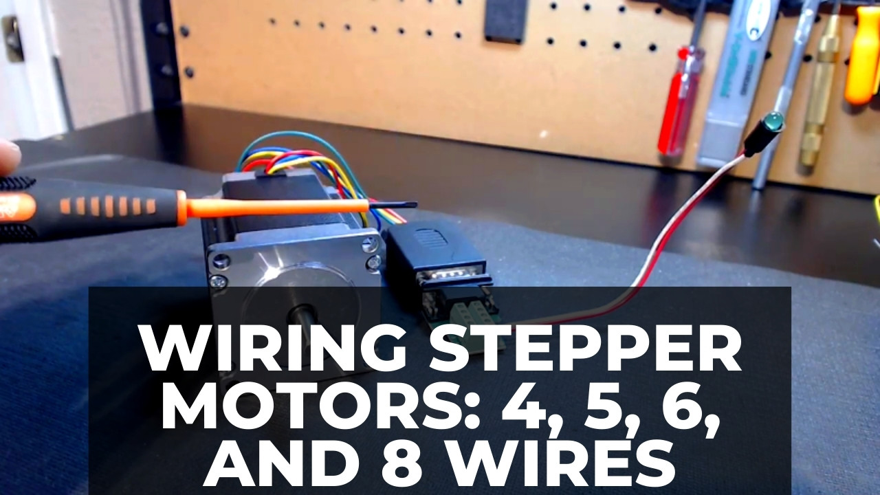
How To Wire A Stepper Motor 4 5 6 And 8 Wires Cncsourced

Omde2 Oms Motion Inc Pdf Catalogs Technical Documentation Brochure

16h5c 5 Phase Stepper Motors 39mm 0 36degree Motionking Stepper Motor
Sustainability Free Full Text Potential Evolution Of The Cooling Market In The Eu27 Uk An Outlook Until 2030

Pop Art Project Self Portrait Art Lesson Plan For 4th Grade Middle School

Bipolar Stepper Motor Driver Electronic Schematic Diagram

Kxfwohy2rd3owm
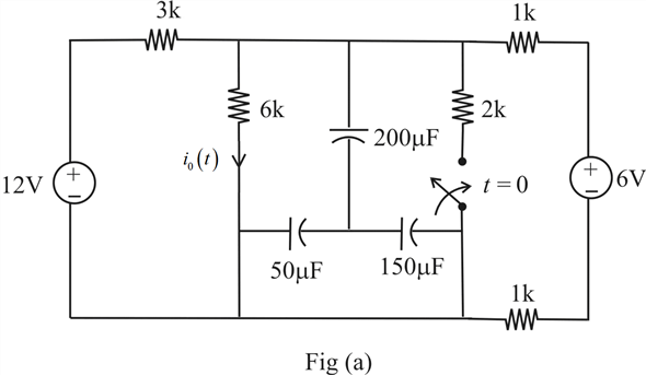
Solved Find Io T For T 0 In The Circuit In Find Io T For T 0 1 Answer Transtutors

Jmc Closed Loop Stepper Motor 3nm Ihss60 36 30 21 38
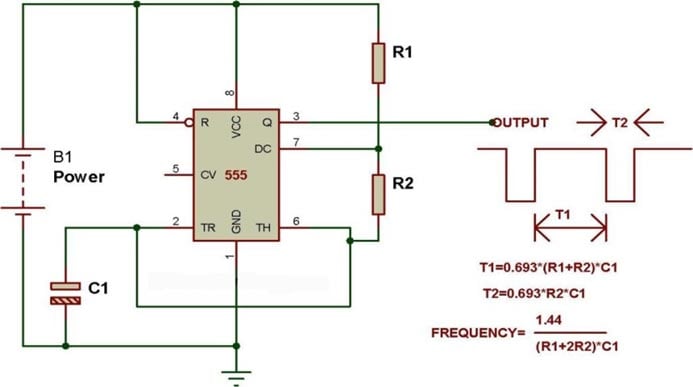
Simple Stepper Motor Driver Circuit Diagram Using 555 Timer Ic

Autel Scanner Maxicom Mk906 Pro 2023 Upgrade Version Of Ms906 Pro Ms9 Autelushops

Stepper Motor Driver Circuit Diagram Schematic Electrical4u

Top 258 Projects Based On Motor
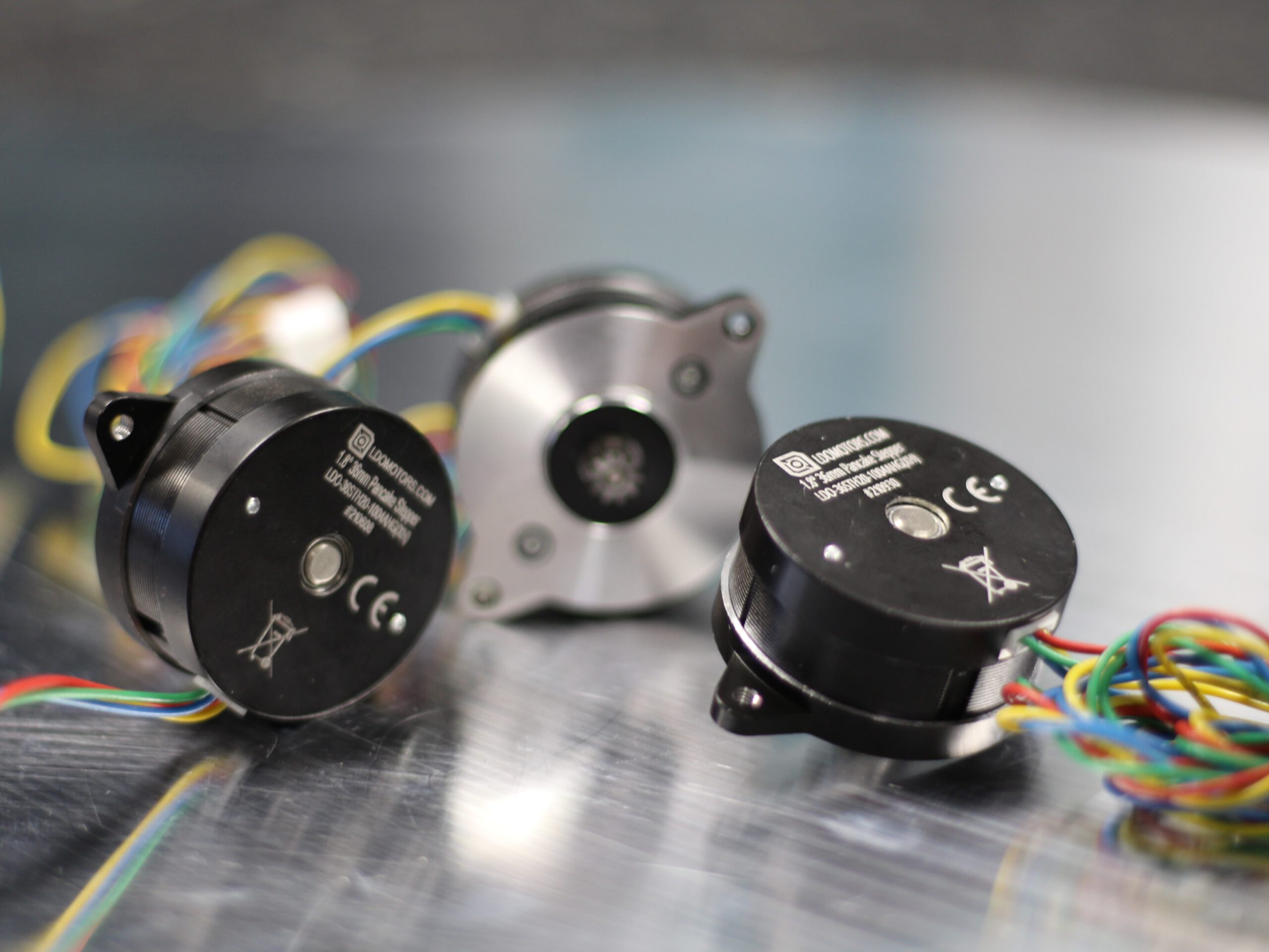
Ldo Schrittmotor 36sth20 1004ahg Cr 3d Leichtgewicht Extrudermotor Ldo
Stepper Motor Working Diagram Types Characteristics Applications Electricalworkbook

Omde2 Oms Motion Inc Pdf Catalogs Technical Documentation Brochure
Simple Stepper Motor Driver Circuit Diagram Using 555 Timer Ic